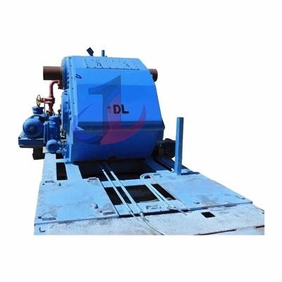
Power End
Rack structure and materials
The GD-600's power unit frame employs a high-strength welded steel frame (Fabricated Steel Frame) instead of conventional cast iron. This design allows thicker steel plates (e.g., A541/T-1 steel) to be used in stress-concentrated areas like the main bearing housing, while thinning in non-load-bearing zones. This achieves a total dry weight of approximately 5,000 lbs (2,270 kg) without compromising rigidity-a critical advantage for oilfield special-purpose vehicles that must comply with highway axle load limits.
The rack incorporates precision crosshead slides, typically fitted with replaceable bronze slides. The bronze material (e.g., SAE 841) features excellent friction reduction and a self-lubricating microporous structure, providing stable crosshead guidance even under splash lubrication while serving as a sacrificial component to protect the expensive rack from wear.
crankshaft and gear transmission system
- Crankshaft Design: The GD-600 employs a **crankshaft-type** construction, unlike the eccentric shaft design found in some compact pumps. The crankshaft is forged from SAE 4330 modified alloy steel (Forged SAE 4330 Modified Alloy Steel). This steel, rich in nickel, chromium, and molybdenum, achieves exceptional toughness and fatigue resistance through heat treatment, enabling it to withstand high-frequency (up to 450 RPM) alternating load impacts.
- Gear reduction: The pump features an integrated gear reduction mechanism with a standard ratio of 4.68:1. This configuration enables the input shaft to operate at a high speed (approximately 2100 RPM), matching the standard RPM range of diesel engines, while the crankshaft drives the plunger at a maximum speed of 450 RPM.
- Flexible Gear Installation: The GD-600 gearbox supports left or right mounting (Left or Right Gearbox Mounting) to accommodate different vehicle chassis layouts (with drive shafts entering from either side). This modular design significantly simplifies the transmission chain layout for on-board pump units. The main gear, made of heat-treated 4140 alloy steel, is bolted to the eccentric hub. This modular design greatly reduces maintenance costs when gears fail.
bearing configuration system
Under high load and high speed conditions, the bearing selection determines the service life of the power end.
- Main Bearing: Heavy-duty roller bearings are employed. These bearings provide superior radial load-bearing capacity compared to ball bearings, effectively supporting the substantial reaction forces exerted on the crankshaft during the pumping stroke.
- Crankpin Bearing: The connection between the connecting rod and crankshaft journal uses a **bronze** journal. Bronze journals excel in splash lubrication and have excellent embedment properties, effectively trapping tiny lubricant particles to prevent journal scoring.
- Crosshead pin bearing: also uses bronze bushing.
Lubrication system: The trade-off between splash and force
The GD-600 employs splash lubrication as its standard lubrication method. The crankshaft and connecting rod rotate at high speed within the crankcase oil reservoir, splashing lubricant onto the crosshead, guide rails, and bearings. To ensure adequate oil supply to critical components, the system typically features an auxiliary oil pump that delivers lubricant to hard-to-reach working surfaces.
For demanding applications (e.g., prolonged high-load operation), the GD-600 may be equipped with or come standard on specific models (e.g., GD-600 AB) with a Pressurized Lubrication System. This system features a dedicated lubrication pump, filter, and oil circuit that delivers clean pressurized oil directly to the main bearing and connecting rod journal, creating a stable hydrodynamic oil film. It provides protection at low speeds while also serving as a critical cooling mechanism.
fluid end
Valve-Over-Valve Design Architecture
The GD-600 typically employs a vertical flow channel design with a **Valve-Over-Valve** configuration.
- Structural Principle: The intake valve is positioned at the bottom, while the exhaust valve is located directly above. This configuration significantly reduces the clearance volume. In high-pressure pumping, fluid compressibility is a critical factor. A smaller clearance volume means less expansion of the compressed fluid retained in the cylinder during the intake stroke, thereby substantially improving volumetric efficiency.
- Material specifications: The hydraulic end cylinder is typically fabricated from SAE 4330 modified alloy steel forgings. The forging process eliminates casting defects, resulting in a dense arrangement of metal grains along the stress direction, which significantly enhances fatigue crack resistance.
- Autofrettage Process: For high-pressure hydraulic ends with small diameters (e.g., 2.75-inch and 3-inch), the GD-600 introduces the **Autofrettage** process as an optional feature. This process applies ultra-high pressure to the inner cavity during manufacturing, causing the inner wall metal to undergo plastic deformation while the outer layer remains elastic. After pressure release, the outer layer's elastic recovery force generates pre-compression stress on the inner layer. During pump operation, this pre-compression stress counteracts the tensile stress caused by fluid pressure, significantly extending the fatigue life of the hydraulic end under high-pressure cyclic loads.
plunger and seal assembly
- Plunger: The plunger diameter ranges from 2.75 inches to 5 inches. To resist wear from fracturing sand and acid fluids, the plunger surface is coated with a hardened layer. The most common coating material is Colmonoy (a nickel-based alloy), which is applied to the base through a thermal spraying process, offering exceptional hardness and corrosion resistance. For high-end applications, ceramic plunger is sometimes used.
- Piston connection: The piston is clamped to the middle rod (Pony Rod) using clamp connections. This design allows maintenance personnel to replace the piston without disassembling the middle rod or opening the power end, significantly reducing on-site maintenance time.
- Packing:
- Adjustable packing: A standard feature that compensates for packing wear by tightening the gland nut.
- Non-adjustable/Spring-loaded packing: An optional design that uses spring force to maintain constant sealing pressure, reducing risks of over-tightening (burnt plunger) or under-tightening (leakage) caused by human error.
- Sealing materials: Common packing types include Style 838 and Style 858 (SuperGold). Style 858 is made of high-temperature resistant nitrile rubber and aramid fiber composite, capable of withstanding 250°F without lubrication and 300°F with lubrication, making it ideal for dry friction or poor lubrication conditions in downhole operations.
Valves and Seats
- Guidance Type: The GD-600 is compatible with both **Wing Guided** and **Stem Guided** valves. The Wing Guided valve features a large flow area, ideal for high-flow applications, while the Stem Guided valve ensures precise positioning, perfect for high-frequency impact operations.
- Valve seat design: The valve seat typically adopts a **fully open (Full Open)** design to minimize flow resistance.
- Materials: The valve body and seat are made of alloy steel with surface carburizing. The sealing insert is typically polyurethane, which is standard due to its excellent wear resistance. For high-temperature or oil-based slurry environments, special rubber inserts such as HNBR are also available.
Performance Parameters and Hydrodynamic Data
The performance of the GD-600 is determined by both the plunger diameter and pump speed. At a maximum speed of 450 RPM, the theoretical output of different plunger configurations is shown in the table below (based on 90% mechanical efficiency and 100% volumetric efficiency):
|
Plunger diameter (inches) |
Displacement per revolution (gal/min) |
100 RPM flow (GPM) |
300 RPM flow (GPM) |
450 RPM flow (GPM) |
Maximum pressure (PSI) |
|
2.75 |
0.463 |
46 |
139 |
208 |
16,845 |
|
3.00 |
0.551 |
55 |
165 |
248 |
14,154 |
|
3.50 |
0.749 |
75 |
225 |
337 |
10,399 |
|
4.00 |
0.979 |
98 |
294 |
440 |
7,962 |
|
4.50 |
1.239 |
124 |
372 |
557 |
6,291 |
|
5.00 |
1.529 |
153 |
459 |
688 |
5,096 |
Analysis: The GD-600's 2.75-inch plunger configuration delivers a pressure capacity of 16,845 PSI, enabling it to handle ultra-high pressure testing and extrusion operations-a capability that surpasses many pumps in its class.
Auxiliary systems and interface configurations
- Inlet manifold: The standard 6-inch inlet manifold features Victaulic (clamp) connectors. These connectors allow quick assembly/disassembly and provide flexibility to absorb pipeline vibrations, making them ideal for frequently mobile workover vehicles.
- Discharge port: WECO thread or flange connection (e.g. 1502 byron) is the industry standard for high-pressure manifold.
- Specialized tools: The pump is typically equipped with a hydraulic end tool kit, including specialized tools such as a valve seat puller, which is essential for rapid field repairs.
Hot Tags: gardner denver 600 pump, China gardner denver 600 pump manufacturers, suppliers, factory