


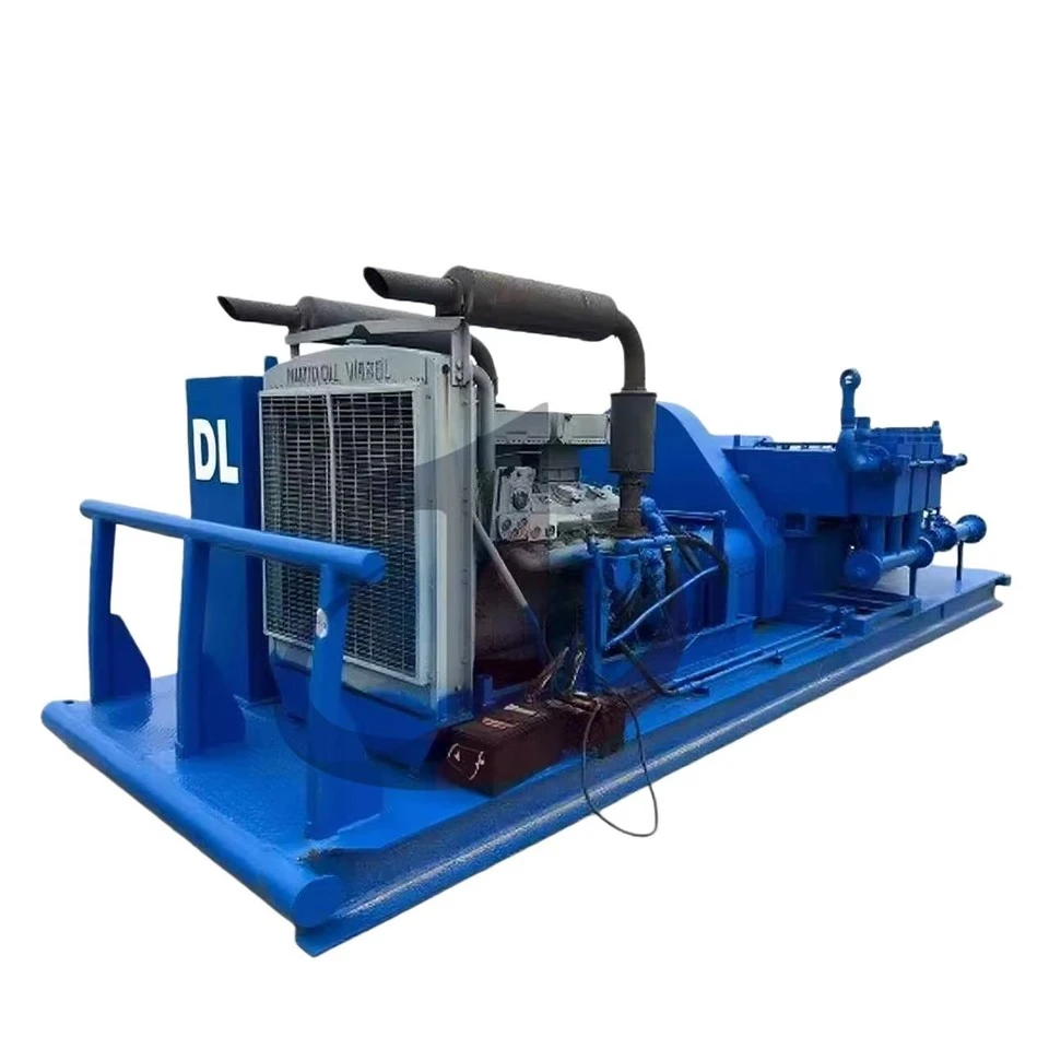
Powertrain Engineering and Mechanical Architecture
Integrated high-strength dynamic frame
The JWS-400 employs a monolithic high-strength steel power frame, a design critical for engineering applications. During high-load pumping operations, the pump body experiences significant alternating loads. In contrast, split or bolted frames may develop minor elastic deformations under cyclic stress. While imperceptible to the naked eye, these deformations can cause microscopic misalignment between the crankshaft and crosshead guide, potentially leading to bearing wear, connecting rod fatigue fractures, or premature failure of the stuffing box. The monolithic frame eliminates joints, delivering exceptional structural rigidity that ensures precise alignment of moving parts under full load.
Furthermore, the frame incorporates an "Open Frame Construction" design, offering significant convenience for maintenance personnel. The large power-end inspection cover allows technicians direct access to critical components like bearings and connecting rods, eliminating the need to remove the entire pump from the support block. This design underscores a strong emphasis on on-site maintainability.
Crankshaft Dynamics and Bearing Configuration
The crankshaft, the heart of the power unit, is equipped with a Double Extended crankshaft in the JWS-400 model.
- Dimensions: Crankshaft diameter 6.00 in (152.4 mm), extension length 10.25 in (260.4 mm), keyway size 1.50 x 0.75 in.
- Design rationale: The dual-shaft extension design enables users to flexibly select power input from either the left or right side based on the vehicle's layout. This proves to be a critical engineering advantage for space-constrained fracturing or cementing vehicles. The 6-inch shaft diameter delivers exceptional torsional strength, capable of transmitting the instantaneous torque peak generated by 400 horsepower without plastic torsion.
In bearing selection, the JWS-400 employs heavy-duty tapered roller bearings as its primary bearing. Unlike ball or cylindrical roller bearings, tapered roller bearings can simultaneously withstand substantial radial loads (from piston thrust) and axial loads (from side forces in bevel gear or chain drive systems). This bearing configuration is particularly critical for systems utilizing bevel gear reduction or chain drives, as both drive methods generate significant axial thrust.
connecting rod and cross head system
The connecting mechanism between the crankshaft and the hydraulic end is a set of precision connecting rod and crosshead mechanism.
- Connecting Rods: Constructed from stainless steel or cast steel with a detachable design. The connecting rod bushings typically feature precision-machined aluminum alloy bushings, which provide excellent sealing properties to trap lubricant particles and prevent crankshaft pin wear.
- Crossheads: Constructed from cast iron with upper and lower oil grooves. The friction pair formed by cast iron and steel guide rails exhibits an exceptionally low friction coefficient and outstanding wear resistance under optimal lubrication. Their primary function is to withstand lateral forces generated by the connecting rod, ensuring that only pure axial thrust is transmitted to the intermediate extension rods at the hydraulic end.
- Intermediate Pull Rod: The JWS-400 features a replaceable stainless steel intermediate pull rod. This is critical as the rod wears out when passing through the oil seal partition. The stainless steel material provides essential corrosion resistance, preventing rust caused by environmental moisture that could damage the oil seal.
chain drive system
A standout feature of the JWS-400 is its standard chain reducer, delivering a 4.667:1 reduction ratio.
- Torque multiplication: This gear ratio reduces the input shaft speed (typically linked to a diesel engine) while amplifying torque by approximately 4.6 times. For example, with a pump's maximum speed of 286 RPM, the input shaft reaches around 1335 RPM – precisely within the high-efficiency torque range of a standard diesel engine.
- Chain drive advantages: Compared to gear reducers, chain drives offer greater flexibility, effectively absorbing common shock loads in underground operations (e.g., pressure fluctuations during slurry pumping with solid particles). Additionally, the chain drive's 30-gallon (113.5-liter) oil capacity ensures sufficient lubrication for heat dissipation and chain cleaning.
physics of lubrication systems
The power end employs a 'Flooded sump, splash distribution' lubrication system.
- Mechanism: As the JWS-400 is an intermittent-duty pump, it does not come with a complex forced-pressure lubrication system. Instead, it uses the high-speed rotation of the crankshaft and connecting rod to stir the lubricating oil in the oil reservoir, creating oil mist and splashing oil flow that covers the crosshead guide rail, wrist pin, and main bearing.
- Limitations and Management: Splash lubrication heavily depends on oil level control. Insufficient oil levels cause inadequate lubrication, leading to catastrophic bearing erosion, while excessive levels result in severe oil agitation loss, causing rapid temperature spikes and foam formation that diminish lubrication efficiency. Thus, the standard "oil level dipstick" and "crankcase breather" are seemingly simple yet critical maintenance components 5. The breather balances pressure fluctuations in the crankcase caused by temperature changes, preventing oil seal leakage.
Hydraulic End Architecture: A Deep Analysis of the Conical Valve System
Forged Steel Material and SAE 4330V Metallurgy
The hydraulic end of the JWS-400 is forged from steel. In high-pressure pump manufacturing, the industry standard material is typically SAE 4330V (vanadium-modified) alloy steel.
- Material Properties: SAE 4330V is a low-alloy steel containing nickel, chromium, molybdenum, and vanadium. The addition of vanadium refines the grain structure, significantly enhancing the material's hardenability and impact toughness. For hydraulic end valve boxes subjected to high-cycle fatigue, impact toughness is critical for preventing crack initiation and propagation in stress concentration zones, such as the intersection of valve seat and plunger holes.
- Manufacturing process: Forging can break the as-cast structure, allowing the metal flow to conform to the part's shape, thereby providing maximum strength in the direction of maximum stress. In contrast, castings often exhibit micro-porosity and gas pores, failing to meet the safety factor requirement of 10,000 psi.
Technical Competition Between Tapered Valve and Cage Valve
Users specifically focus on the hydraulic end of the tapered valve. The JWS-400 platform features two primary valve configurations: cage valves and tapered valves (also known as full open valves). These designs differ fundamentally in fluid mechanics and mechanical structure.
The Limitations of Caged Valve
In traditional cage valve designs, the valve seat is mounted on the valve box's step, secured by a separate cage above and fixed by the valve cover's force. The cage typically provides the valve's guidance.
- Disadvantages: The cage occupies part of the fluid passage, increasing flow resistance. At high flow rates, this leads to higher pressure drop and reduced volumetric efficiency of the pump. Additionally, the mechanical contact surface between the cage and the valve cover is prone to micro-wear under prolonged vibration.
Engineering Advantages of Conical Valve (Fully Open Type)
The tapered valve design, exemplified by the Mission Service Master series, completely eliminates the need for separate cages.
- The interference fit mechanism: The valve seat's outer cylindrical surface features a precision taper (typically API standard taper) that precisely mates with the corresponding tapered bore machined in the hydraulic end valve housing. The valve seat is wedged into the valve housing through this interference fit. By leveraging substantial friction and the wedge effect, the valve seat resists fluid impact without loosening.
- Hydrodynamic Optimization: The removal of the cage allows full fluid passage (Full Open), significantly reducing turbulence and resistance during fluid entry into the pump chamber. When the JWS-400 operates at maximum 286 RPM, the suction time window is extremely brief (approximately 0.1 seconds). The tapered valve's unobstructed flow path substantially lowers the required net positive suction head (NPSH), thereby minimizing cavitation risks. Cavitation not only reduces pump efficiency but also generates high-pressure micro-jets during bubble collapse, which are primary contributors to internal wall pitting and fatigue cracking in hydraulic systems.
- Self-locking effect: As the pumping pressure increases, the downward hydraulic force acting on the valve seat further presses it into the conical bore, enhancing the sealing effect and effectively preventing high-pressure fluid from "washing out" (Washout) through the valve seat's outer circumference.
Frictional Design of Valve Components
The JWS-400 employs a Mission Service Master valve assembly featuring precision-engineered valve bodies and seats.
- Urethane Inserts: The valve's sealing mechanism relies not on metal-to-metal contact but on urethane inserts embedded in the valve body. Compared to nitrile rubber, urethane exhibits superior tear resistance and wear resistance, making it particularly suitable for fluids containing proppants (e.g., fracturing sand). However, urethane is temperature-sensitive and typically operates within a range of 170°F to 180°F (approximately 77°C to 82°C). If the fluid temperature exceeds this range, the inserts may soften and fail, leading to leakage.
- Valve seat hardening: The valve seat surface is typically carburized to achieve Rockwell C 60 hardness. This exceptional hardness is designed to resist abrasive wear caused by high-speed fluid entrainment of sand particles during valve closure.
plunger and packing system
For high-pressure applications (>5,000 psi), the JWS-400 must be equipped with a plunger instead of a piston.
- The key difference is that the piston features a rubber-lined bowl moving reciprocally within the cylinder liner, with sealing occurring between the bowl and liner. In contrast, the plunger is a hardened metal rod sealed by a stationary stuffing box.
- Packing Box Design: The JWS-400's packing box is constructed from ductile iron and features a threaded gland design. The packing typically consists of a "lip type" or V-ring, often equipped with a spring-loaded mechanism 10. The spring provides a constant axial preload, automatically compensating for wear to maintain radial sealing pressure on the plunger. This design is essential for minimizing maintenance frequency.
- Plunger Lubrication: The 'Plunger Lubricator' specified in the parts list is a critical component for high-pressure operations. It delivers lubricating oil to the rear of the stuffing box, not only reducing friction heat by lubricating the plunger surface but also flushing out fine sand particles that might embed in the packing, thus preventing surface scratches.
Analysis of Hydraulic Performance and Operating Parameters
The performance of JWS-400 is determined by both mechanical torque limits and hydraulic pressure limits. Understanding these limitations is essential for safe operation.
The Balance between Pressure and Displacement
While the hydraulic end can achieve a rated pressure of 10,000 psi, this doesn't guarantee that the pressure will be maintained at all displacement levels.
- The output pressure of the pump is inversely proportional to the cross-sectional area of the plunger.
4.5-inch plunger: maximum displacement configuration. Under this setup, the pump's rated pressure drops significantly below 10,000 psi, limited by the 400 HP total power input and the connecting rod's rated load.
3.75-inch or smaller plungers: To achieve 10,000 psi working pressure, smaller-diameter plungers must be used. This is not only to reduce circumferential stress on the hydraulic side but also to maintain the piston thrust (Rod Load) within the power side's rated range.
Table 1: Key Performance Parameters Comparison of JWS-400
|
parameter |
English unit |
metric unit |
remarks |
|
Rated power (286 RPM) |
400 BHP |
298 kW |
|
|
maximum working pressure |
10,000 psi |
68,950 kPa |
It needs to be used with a small plunger. |
|
maximum piston diameter |
4.5 in |
114.3 mm |
|
|
maximum piston diameter |
5.5 in |
139.7 mm |
Only for low-pressure conditions |
|
stroke length |
7 in |
177.8 mm |
|
|
maximum speed |
286 RPM |
286 RPM |
|
|
intake flange |
6" ANSI 150 RF |
- |
Low-pressure inhalation |
|
discharge flange |
3-1/16" API 6BX |
- |
10,000 psi high pressure |
Pulsation and damping
As a three-cylinder single-acting pump, the JWS-400 generates inherent flow pulsation (approximately 23% of the average flow) during operation. If this pulsation is not controlled, it can cause severe mechanical vibrations in the high-pressure manifold, leading to fatigue failure.
Suction Stabilizer: Installed at the suction inlet to absorb pressure fluctuations caused by fluid acceleration, ensuring complete liquid filling in the cylinder and preventing cavitation.
Discharge Dampener: Installed at the discharge port, this device uses a nitrogen-precharged bladder to absorb high-pressure pulsation peaks, ensuring a steady liquid flow output.
Maintenance, Tools, and API 7K Compliance
The maintenance strategy for JWS-400 centers on replacing 'expendables' -components designed to self-sacrifice for the protection of the expensive forged steel hydraulic end. All critical load-bearing components and pressure control elements must comply with the API Spec 7K 'Drilling and Well-Service Equipment' standard.
Special Maintenance Procedure of Conical Valve Seat
The greatest challenge in designing tapered valves is the replacement of the valve seat. Since it relies on a high-strength interference fit for fixation, the valve seat cannot be removed as easily as in cage valves.
- Specialized tools: The documentation explicitly states that the taper valve seat must be removed using the M-1100 hydraulic puller with the M-1097 puller head.
- Operational Risk: Do not attempt to forcibly remove the valve seat using flame cutting or rudimentary mechanical tools. Flame cutting may damage the metallurgical structure of the heat-treated valve housing, reducing its structural integrity. Mechanical force could also scratch the inner surface of the conical bore. Any damage to the conical bore will prevent the new valve seat from achieving a perfect seal, resulting in leakage and rapid failure of the entire hydraulic system.
- Installation Guidelines: When installing a new valve seat, ensure the conical bore of the valve housing is completely clean and dry (oil-free and water-free). Any grease may form a lubricating film between the conical surfaces, reducing friction and causing the valve seat to loosen under high-pressure impact. Typically, a dedicated hammer tool is required to pre-tighten the valve seat, followed by final tightening and positioning using the pump's own hydraulic pressure.
List of consumables and interchangeability
The JWS-400's consumables include V-belts, V-belts seats, plunger packing, and cylinder liner seals. A wide range of third-party suppliers offer API 7K-compliant replacement parts (e.g., Goldenman, Better, etc.). This comprehensive component ecosystem significantly reduces the JWS-400's lifecycle operational costs.
Table 2: JWS-400 Standard Maintenance Parts and Tools List
|
Component Name |
Example of part number |
maintenance instruction |
|
conical valve seat disassembly tool |
1714291 / M-1100 |
Hydraulic Drive Prevents Pump Body Damage |
|
packing gland assembly |
1714310-12 |
Includes a cover, seal ring, and other components |
|
plunger (hard coating) |
1715158 |
The coating wear should be checked regularly. |
|
intermediate draw bar |
1714296 (OEM) |
connecting crosshead and plunger |
Common Fault Modes and Prevention
Hydrodynamic end cracking: the most common catastrophic failure, typically occurring at stress-concentrated cross holes. Preventive measures include regular ultrasonic or magnetic particle testing (NDT) and avoiding overpressure operation.
Leakage from the valve seat: This occurs due to improper installation or failure of the sealing insert. Preventive measures include strictly following the installation cleaning procedure and promptly replacing worn polyurethane inserts.
Power unit overheating: typically caused by low oil level or contaminated lubricating oil. Strictly follow the oil change schedule and monitor crankcase temperature.
Market positioning and application scenarios
The JWS-400 occupies a unique niche in the downhole pump family. While modern fracturing operations typically use quintuplex pumps (over 2000 horsepower), the JWS-400 remains indispensable for smaller-scale operations.
- Cementing: This process requires precise displacement control and medium-to-high pressure, with the JWS-400's 400 horsepower providing just the right amount.
- Coiled tubing operations typically require sustained circulation pressure. The JWS-400's compact design allows easy installation on the coiled tubing truck chassis.
- Acidizing: The hydraulic end of the forged steel and stainless steel components provide the essential corrosion resistance, combined with acid-resistant packing and rubber seals, enabling effective acid pumping.
The JWS-400 delivers higher power density than its counterparts JWS-340 or JWS-165, while offering superior mobility and deployment flexibility compared to larger pumps. Its 4.667:1 chain ratio design enables direct compatibility with standard truck diesel engine power outputs, streamlining the transmission system design.
Hot Tags: nov jws-400 tapered valves and seats pump, China nov jws-400 tapered valves and seats pump manufacturers, suppliers, factory


